A pressure transmitter works by converting the physical pressure of a gas or liquid into a standardized electrical signal (most commonly 4–20 mA, often with HART or MODBUS on top). In most industrial designs, the process pressure deflects a metal diaphragm, that force is transferred to a sensor element (often piezoresistive), and onboard electronics linearize, temperature-compensate, and scale the signal to the chosen output.
What a pressure transmitter is doing in one sentence
Pressure → diaphragm movement → sensor changes electrically → electronics correct + scale → output signal.
That’s the core principle whether you’re measuring gauge pressure, absolute pressure, differential pressure, level (hydrostatic pressure), or flow (via DP).
The main building blocks inside a pressure transmitter
1) Process connection and diaphragm (the “wet end”)
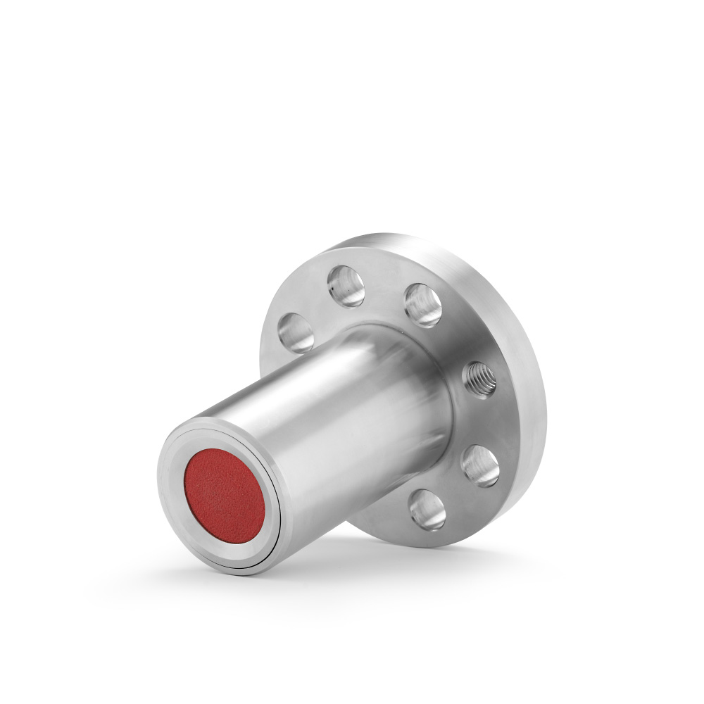
The pressure from the process acts on a diaphragm (commonly stainless steel, Hastelloy, tantalum, gold-plated options for special media). The diaphragm is designed to be robust and, in many sanitary/dirty services, shaped to resist damage and be easier to clean.
Why it matters: the diaphragm is the first line of defense—its material and geometry largely decide corrosion resistance, cleanability, and survivability in abrasive or sticky media.
2) Pressure transfer (often oil-filled)
Many industrial transmitters use a small internal volume filled with silicone oil between diaphragm and sensor. When pressure pushes the diaphragm, the oil transfers that pressure to the sensing element while isolating it from the process media. Because the fill volume can be very small, diaphragm movement is tiny and performance can be stable.
Some designs are “direct” in the sense that the process connection is integrated without external seals or complicated pressure intermediates, which reduces error sources and improves robustness.
3) The sensing element (where pressure becomes an electrical change)
A very common technology is piezoresistive sensing. Pressure-induced mechanical strain changes the resistance of elements arranged in a Wheatstone bridge, producing a small millivolt signal proportional to pressure.
Other sensing principles exist (capacitive, resonant, etc.), but piezoresistive is widely used because it offers a strong signal, good dynamic response, and solid accuracy when paired with compensation electronics.
4) Reference pressure: gauge vs absolute
A transmitter must know what it’s measuring relative to:
- Gauge pressure (relative): referenced to ambient atmosphere. Typically the back side of the sensor is vented so the transmitter outputs “pressure above atmospheric.”
- Absolute pressure: referenced to a sealed vacuum (no atmospheric vent).
Practical takeaway: gauge transmitters need their vent/reference path kept clear and protected from moisture and blockage; absolute versions avoid that but measure absolute pressure, not “overpressure.”
5) Signal conditioning and digital processing (the “transmitter” part)
The raw bridge signal is small and temperature-sensitive. Modern transmitters therefore use microprocessor-based electronics to:
- amplify and digitize the sensor signal
- measure temperature (often inferred from sensor characteristics and/or a temperature sensor)
- apply temperature compensation and non-linearity correction using calibration data stored from factory calibration
- apply scaling and transfer functions (linear, square-root, etc.)
- generate the final output as 4–20 mA and optionally expose digital values via HART or MODBUS
This is why a transmitter is more than a “sensor”: it provides a stable, standardized measurement that a PLC/DCS can trust.
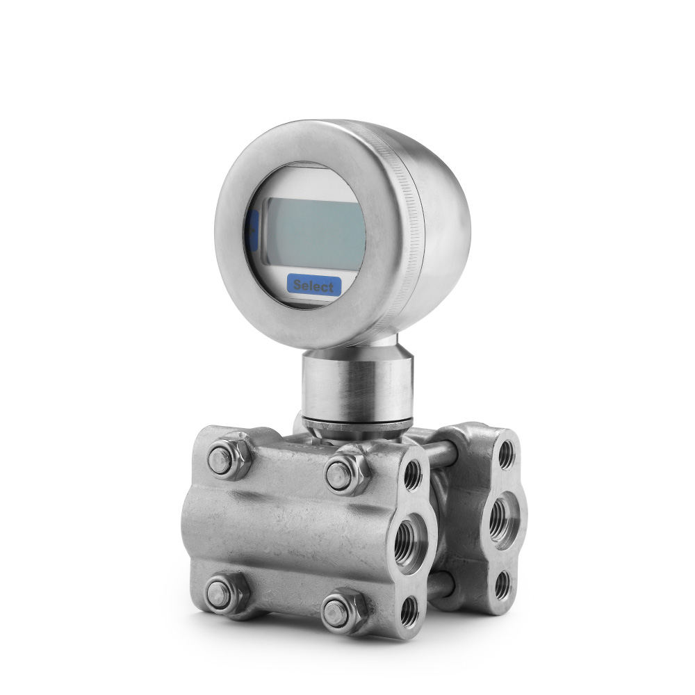
Differential pressure transmitter working principle (DP)
A differential pressure transmitter measures the difference between two pressures: P(+) – P(-).
How DP is physically created inside the transmitter
A common DP architecture uses:
- two separating diaphragms (one for each side)
- oil-filled chambers and capillaries transferring pressure to a central sensor
- an overload membrane that limits how much differential pressure actually reaches the sensor during overload events
Why overload protection is a big deal in DP
In real plants, one side can see spikes, line hammer, or incorrect valve sequencing. The overload membrane concept allows the transmitter to tolerate overload by mechanically preventing unlimited differential force across the sensor.
Where DP transmitters are used most:
- flow measurement across an orifice/venturi
- filter monitoring (ΔP rising = clogging)
- level in pressurized/closed tanks (DP separates static pressure from hydrostatic head)
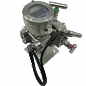
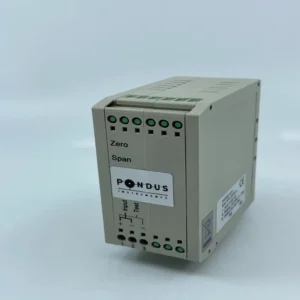
If you need digital DP with multiple outputs/communications, a typical example in the Pondus range is PT600RSH
A practical example: level measurement using pressure (hydrostatic principle)
For an open tank, level is proportional to bottom pressure:
P=ρ⋅g⋅hP = \rho \cdot g \cdot hP=ρ⋅g⋅h
For a pressurized tank, the clean way is often differential level: measure pressure at the bottom (static + head) and subtract the gas space pressure (static). That’s exactly the type of use case where DP transmitters (or two linked sensors) are applied.
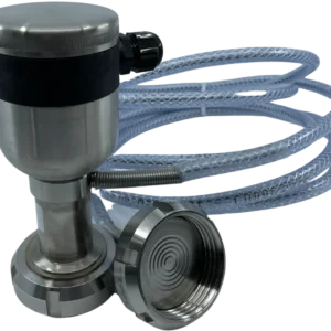
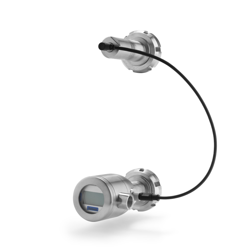
For sanitary, pressurized tank level with remote connection, transmitters like PT60 type T are designed to measure differential pressure via plus/minus diaphragms and a capillary to the minus side.
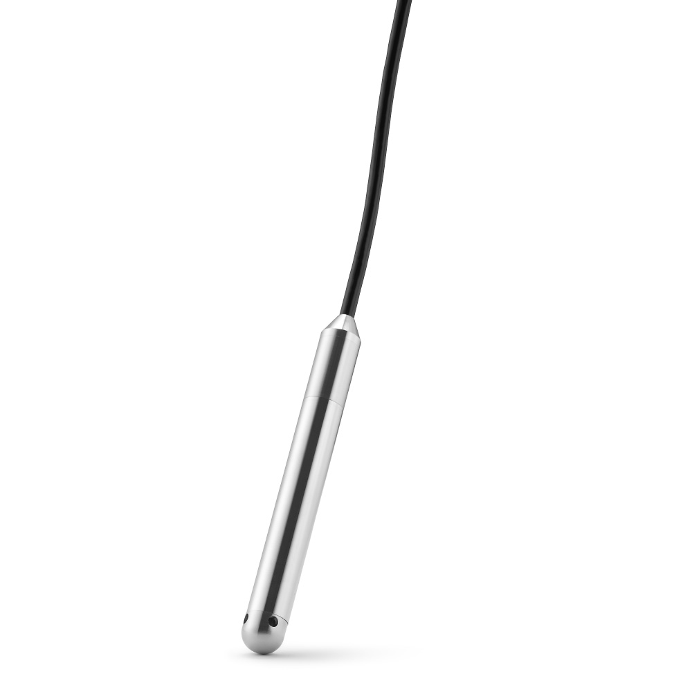
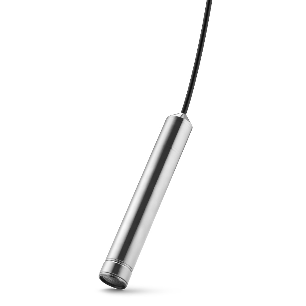
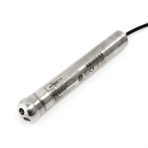
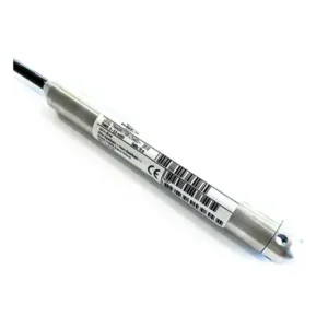
For submersible level measurement, the same pressure-to-signal principle is packaged in a probe, e.g. (“LT100″linkhere) or (“LT10″linkhere), where the diaphragm senses hydrostatic pressure and electronics compensate and output 4–20 mA (often with HART on certain models).
Why temperature, mounting, and capillaries can influence readings
Even with compensation, installations matter:
- Ambient temperature gradients can affect capillary-filled systems if the capillary and transmitter body experience different temperatures (seen most in differential/remote setups).
- Mounting orientation / head pressure effects can shift the “zero” for DP/level setups (especially when plus and minus ports are at different elevations).
- Static pressure changes can temporarily influence DP readings if one side responds faster than the other (capillary dynamics).
This is also why many modern transmitters include a convenient way to re-zero after installation or maintenance.
Zero shift and “autozero” (what it is and why it exists)
Over time, a transmitter can show a small zero offset due to mounting stresses, diaphragm effects after cleaning, or minor mechanical influence. Some transmitters implement an autozero function that lets you quickly reset the 4 mA point to the intended “zero pressure” condition—without needing to do it in the control system.
Examples described in Pondus documentation include initiating autozero by a button press or by shorting specific pins/cables for a set time.
If your application involves frequent washdown/CIP or occasional diaphragm impact risk, it’s worth considering transmitters with an easy field re-zero method, such as PT600 or PT03RS, depending on range and interface needs.
Key considerations when choosing a pressure transmitter
Media compatibility
- diaphragm material selection (corrosion, abrasion, hygienic compliance)
- risk of hydrogen ion effects in certain media (sometimes addressed with special diaphragm options)
Pressure type and reference
- gauge vs absolute
- DP vs single pressure
Range and overload
- choose a range where normal operation sits comfortably inside span
- ensure overload ratings match real-life upsets (especially for DP)
Output and integration
- 4–20 mA only
- 4–20 mA + HART
- MODBUS/RS485 where appropriate
Examples of multi-interface transmitters are described in the PT600 family documentation.
Installation realities
- temperature gradients (especially with capillaries)
- venting needs for gauge transmitters
- vibration, washdown, and cleaning routines
Conclusion and CTA
The working principle of a pressure transmitter is straightforward—diaphragm deflection is converted by a sensor into an electrical signal, then electronics compensate and scale it into a standard output like 4–20 mA (with optional digital communication). The real performance comes from how well the diaphragm, pressure transfer method, sensor technology, and compensation electronics match your media, temperature conditions, and installation.
Have more questions or need guidance on choosing the right pressure transmitter? Get in touch with Pondus Instruments, and we’ll help you find the solution that best fits your needs.