A flow transmitter measures how much fluid is moving through a pipe by sensing a pressure-based signal—most commonly the differential pressure (ΔP) created by a primary element such as an orifice or Venturi—and converting it into a linear flow output (typically 4–20 mA with HART/Modbus). The transmitter often performs built-in square-root extraction so that ΔP (which is proportional to flow²) becomes a signal proportional to flow.
The essentials in one minute
1) Create a measurable signal. A primary element in the line causes a small pressure drop that varies with flow. A differential-pressure (DP) transmitter senses this ΔP across two ports. Inside a modern DP transmitter, each side of the process is isolated by thin diaphragms; pressure is transmitted through silicon oil via capillary tubes to a piezoresistive sensor. This design protects the sensor from shocks and overloads.
2) Condition and linearize. Microprocessor electronics measure the sensor bridge, temperature-compensate, and apply a selectable transfer function—linear or square-root—before generating a 4–20 mA signal and communicating digitally (HART/Modbus).
3) Output flow. With square-root enabled and the transmitter ranged to the primary element, the 4–20 mA (and digital) output is proportional to flow. Many units also support local display and remote configuration.
What the DP flow transmitter actually senses
- Sensing stack: Two process pressures act on separating diaphragms; a central sensor “feels” the difference through oil-filled capillaries. An internal overload membrane limits transmitted ΔP during surges, protecting the sensing element.
- Why square-root? For conventional primary elements, ΔP ∝ flow². Built-in square-root extraction inside transmitters like Pondus PT series linearizes the output to flow.
Signal processing and outputs
Modern electronics measure the sensor bridge and temperature, apply factory calibration and temperature/linearity compensation, then compute the chosen transfer function and drive the 4–20 mA loop; values are also available via HART and Modbus.
Practical setup steps
- Select the primary element and range. Size the primary element to generate a usable ΔP over the operating flow range. In your transmitter, enable square-root if you use a head-type element (orifice, Venturi, pitot).
- Plumb high/low correctly and keep impulse lines short/clean to avoid lag or plugging.
- Compensate when needed. For gases/steam, add density/temperature/pressure compensation in the control system or use a multivariable strategy (the transmitter already performs its own internal temperature compensation on the sensor).
- Commission and verify. Use loop checks and trend the live DP while varying flow to confirm direction and scaling.
- Zero correctly. After installation or cleaning, run a zero routine to remove mounting/orientation effects. Pondus transmitters include an Autozero—just short two terminals or press the button for ~10 s to reset zero.
Choosing a Pondus Instruments solution (examples)
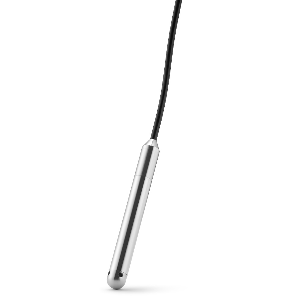
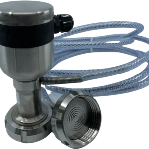
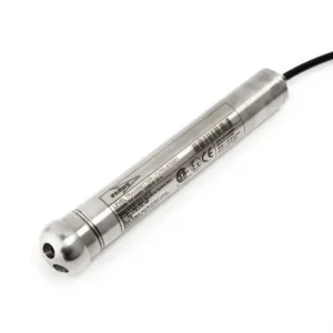
- Hygienic DP flow: For sanitary lines, a DP transmitter such as (“PT60 type T“) measures ΔP via plus/minus diaphragms and supports 4–20 mA with HART. Pair with a sanitary primary element in dairy or beverage services.
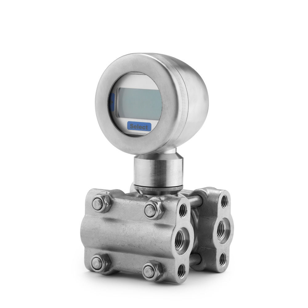
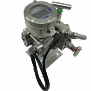
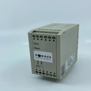
- General-purpose DP/flow with rich I/O: (“PT600RSH“) offers 4–20 mA + HART + Modbus, selectable square-root, temperature/linearity compensation, optional display, and Autozero—suited to most industrial DP flow applications.
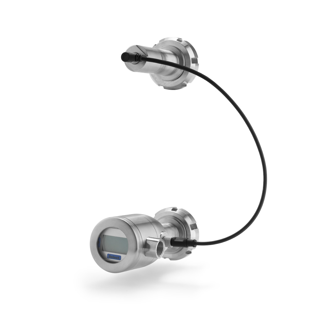
- Need to compute a differential using one remote sensor? Use display D10RSH, which connects a remote sensor and calculates the differential—useful when the low-side tap must be remote.
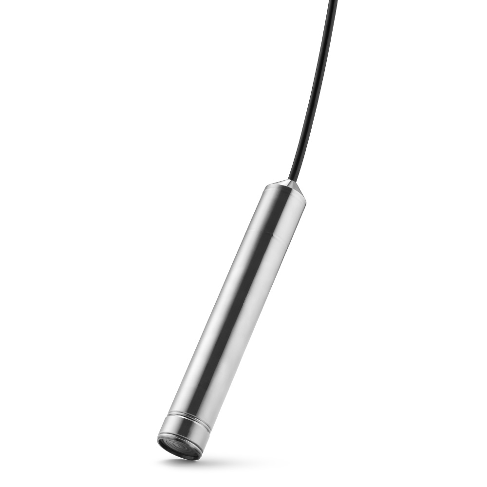
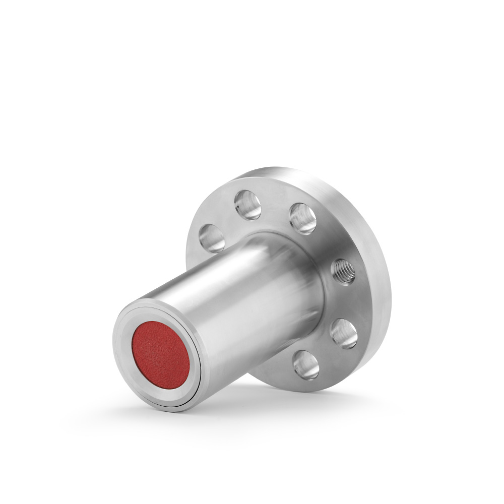
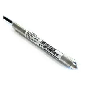
- Compact, cost-effective pressure source for flow calculations: (“PT03RS“) provides 4–20 mA plus Modbus and an Autozero function when you need a small form factor for auxiliary measurements.
Installation and maintenance tips
- Keep the sensing path dry and clean. Avoid gas bubbles (in liquids) and liquid pooling (in gases) in impulse lines.
- Minimize temperature gradients across capillaries; large ambient swings can bias readings if one side is much colder/warmer than the other (a known influence on remote capillaries).
- Use Autozero after service (e.g., after high-pressure washdowns or if the diaphragm has been contacted) to eliminate zero shift.
- Leverage diagnostics and digital comms (HART/Modbus) for configuration and verification without process interruption.
Summary
A flow transmitter converts a pressure-based signal—most commonly ΔP from a primary element—into a linear, temperature-compensated flow output. By sensing ΔP with oil-isolated diaphragms, applying square-root extraction, and sending a 4–20 mA/HART/Modbus signal, it gives your control system a stable, scalable measure of flow.