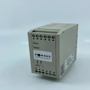
To calibrate a pressure transmitter: isolate it from the process, vent and equalize pressure, apply the lower-range pressure (LRV) and set zero, apply the upper-range pressure (URV) and set span, then verify points (0%, 25%, 50%, 75%, 100%) and document the as-found/as-left values. On Pondus Instruments transmitters you can do zero and span either locally (buttons), via HART/MODBUS, or—when available—by using the Autozero feature to set 4 mA at the true zero condition.
Preparation and safety
- Isolate and depower as needed
Bypass the loop or put the control system in manual. Close process valves or use a 3-/5-valve manifold on DP installations. Depressurize and vent the impulse lines safely.
- Warm-up and stability
Power the transmitter for several minutes so electronics reach a stable temperature before you start adjustments. (Applies to all microprocessor-based PT600/PT03/LT series.)
- Reference standards
Use a traceable pressure source (hand pump/deadweight tester) and a calibrated indicator. Match the medium (air, water) and temperature to your application when possible, to reduce offsets.
Step-by-step calibration (gauge or absolute pressure)
- Hook up
Connect the transmitter to a precision source and meter in the 4–20 mA loop (or read digitally via HART/MODBUS). PT600 and PT03 support both analog and digital reads; LT100 supports HART.
- Zero at LRV
Apply the LRV pressure (often true zero for gauge).
- PT600 / PT60 / PT03: Use local buttons or digital comms to adjust zero. Many models also offer Autozero: place the diaphragm at the condition that should equal 4 mA and trigger Autozero (see below).
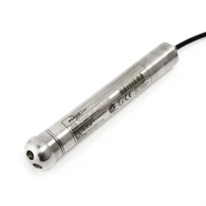
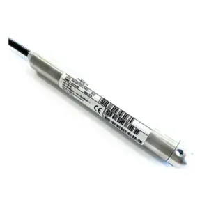
- LT10 / LT100 (submersible level): Adjust zero and span in the electronics box (LT10) or via HART (LT100).
- Span at URV
Apply the URV pressure and adjust span to 20.00 mA. On LT10, span and damping are set with straps and potentiometers; on PT600 and LT100 you can set span via HART/MODBUS or display. Repeat zero/span once because they interact slightly.
- Point check
Check 0/25/50/75/100% points up and down. Results should meet your acceptance criteria (e.g., ≤±0.1% or instrument spec). Document as-found and as-left.
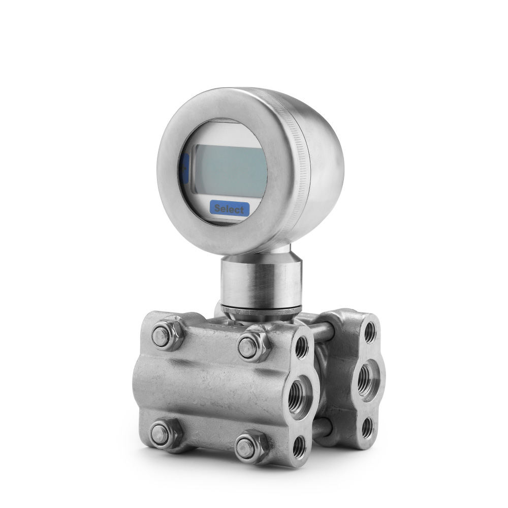
Differential pressure (DP) specifics
- Equalize first
With a 3-valve manifold: close high/low block, open equalize, vent, then apply LRV/URV differentials as needed.
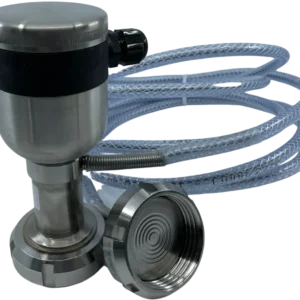
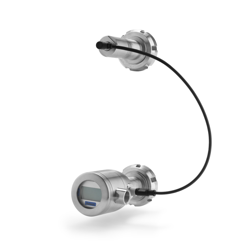
- Mounting effects
After installation, a DP with remote/capillary sides (e.g., PT60 type T) can show an offset due to elevation or temperature differences; zero the transmitter in place to remove mounting dependence.
- Static pressure steps
Be mindful of static pressure influence during rapid changes, especially when one side is via a capillary; allow stabilization before final readings.
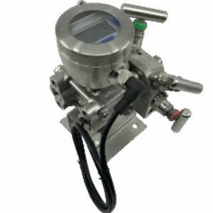
- PT600 DP models
PT600RSH DP units can be configured and zeroed via display, HART, or MODBUS; overload membranes protect the sensor during calibration/pressurization steps.
Using Autozero on Pondus transmitters (when available)
Autozero removes zero shift from mounting, cleaning, or mild diaphragm contact. Typical triggers:
- PT600/PT600RSH: Place the sensor at the desired 4 mA condition and press the front button or short M12 pins 7–8 for ~10 s. Can also be done via HART/MODBUS or display.
- PT03RS/FD: Place in free air (zero pressure) and short M12 pins 3–4 for ~10 s to reset 4 mA to zero pressure.
- General guidance: Use Autozero after cleaning, after any mechanical contact, or as part of annual maintenance.
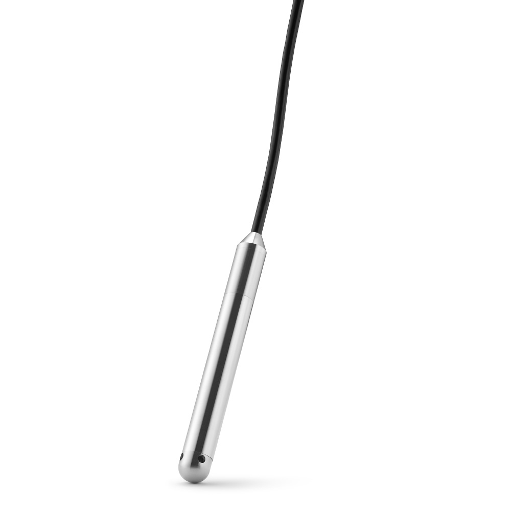
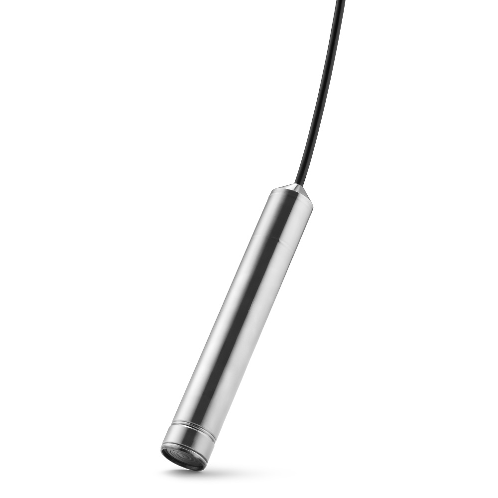
Submersible level transmitters (LT10/LT100) notes
- Where to adjust
- LT10: Adjust zero/span/damping inside the electronics housing; test terminals allow current checks.
- LT100: Perform adjustments via HART (PI100 or a standard hand terminal).
- Cable and venting
Ensure the vent/reference arrangement is correct (LT100 vent tube; LT10 uses dual-sensor atmospheric compensation). Incorrect venting can look like a calibration error.
Best practices to get a good calibration
- Stabilize temperature: If one side of a DP has a long capillary, insulate it to limit thermal transients before zeroing.
- Damping/time constant: Use transmitter damping to suppress noise; LT10 offers 0.1 s or 3 s via jumper.
- Communications: For configuration and saving records, use HART or MODBUS (PT600/PT03; LT100 HART). Pondus tools like (PI200PS/PSD) and (MEP7 Modbus Tool) simplify set-up and verification.
- Autozero after cleaning: High-pressure washing can nudge zero; use Autozero rather than re-ranging your PLC/DCS.
Troubleshooting common issues
- Zero won’t hold → Check for trapped pressure, plugged impulse lines, wrong venting, or temperature gradients (DP with capillary). Use Autozero only after the physical issues are resolved.
- Span error → Confirm the reference source, medium density (for level), and that you’re applying the actual URV. Re-check once after adjusting—zero and span interact slightly.
- No HART/MODBUS comms → Ensure the required loop resistor for HART and correct RS485 wiring for MODBUS; note RS485 is not permitted in Ex zones for certain models.
Subtle product guidance
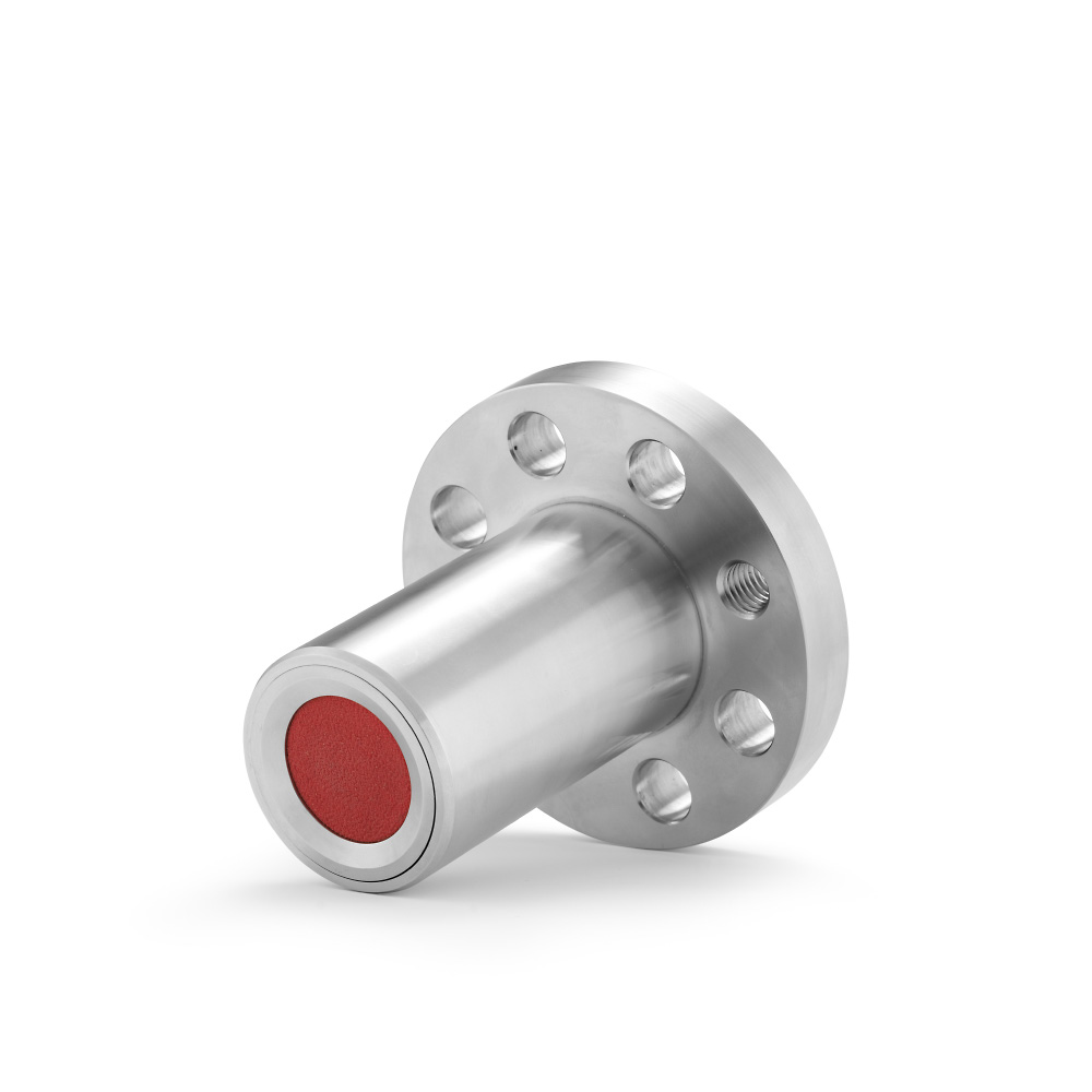
- For hygienic DP level on pressurized tanks, consider (PT60 type T). It’s designed for plus/minus diaphragms with capillary and details the thermal/static dependencies you’ll calibrate out.
- For general gauge/DP/level with digital tools and Autozero, see (PT600 series).
- For compact universal pressure, (PT03RS) provides Autozero and MODBUS for quick field calibration.
- For submersible level, choose (LT10) if you prefer local trim or (LT100) for HART-based calibration.
Conclusion and CTA
Calibrating a pressure transmitter comes down to isolating, zeroing at LRV, spanning at URV, verifying intermediate points, and documenting. On Pondus Instruments devices you can do this with local keys, HART/MODBUS, or Autozero—use the method that best fits your installation and maintenance routine. Have more questions or need guidance on choosing the right pressure transmitter? Get in touch with Pondus Instruments, and we’ll help you find the solution that best fits your needs.