Reading a pressure transmitter involves interpreting its output signal, whether analog or digital, to determine the measured pressure. This process includes setting up the transmitter, understanding its signal type, and converting the signal into a meaningful pressure reading.
Steps to Read a Pressure Transmitter
1. Understand the output signal
Pressure transmitters typically output:
- 4–20 mA analog signal:
- The signal corresponds to the pressure range of the transmitter.
- For example, 4 mA might represent 0 bar, and 20 mA might represent 10 bar.
- Digital signals:
- Protocols like HART, MODBUS, or PROFIBUS provide digital data that can include pressure, temperature, and diagnostics.
- Voltage signals:
- Less common in industrial applications (e.g., 0–5 V or 0–10 V).
2. Connect the transmitter to a system
- Analog signal setup:
- Connect the transmitter to a 24V DC power supply.
- Use a multimeter in series with the loop to measure the 4–20 mA current.
- Ensure the wiring matches the transmitter’s specifications (e.g., polarity, grounding).
- Digital signal setup:
- Use a compatible communication device, such as a HART modem or a MODBUS interface.
- Connect the device to a PC or handheld terminal with the appropriate software (e.g., HART communicator or MODBUS tool).
3. Interpret the signal
For 4–20 mA analog output:
Convert the signal to pressure using the scaling equation:

Where:
- I: Measured current in mA
- Pmax: Maximum pressure range of the transmitter
- Pmin: Minimum pressure range of the transmitter
- Transmitter range: 0–10 barMeasured signal: 12 mA

For digital output:
Use the communication software to display pressure readings directly.
Digital protocols often provide additional parameters like temperature and diagnostics.
4. Verify and calibrate (if needed)
- Check the pressure transmitter against a reference gauge or calibrator to ensure accuracy.
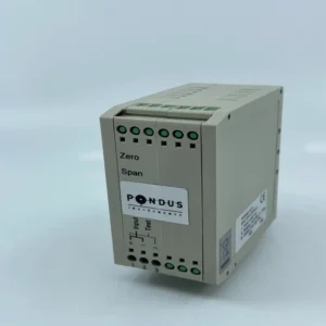
- For analog transmitters, adjust the zero and span settings if necessary.
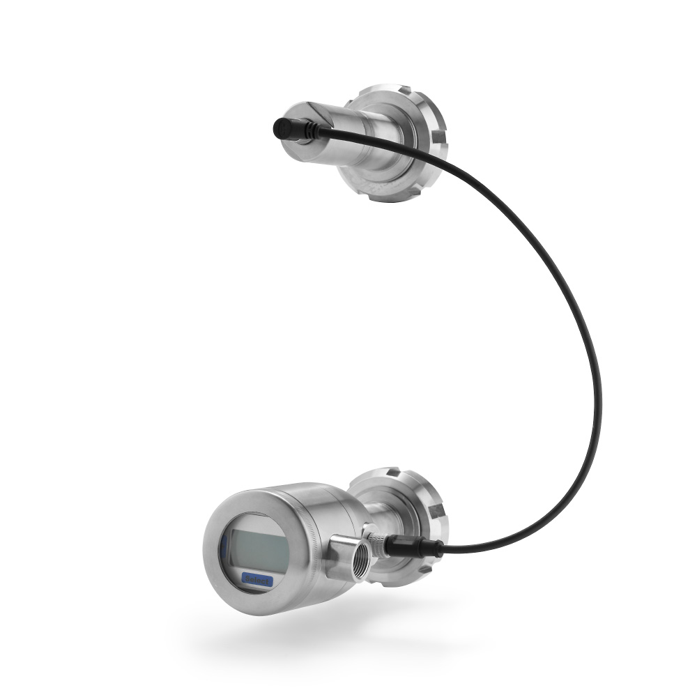
- Example: The PT600 series includes an autozero function to simplify calibration.
Tools Needed
- Multimeter (for current signals).
- HART communicator or MODBUS tool (for digital signals).
- Power supply (24V DC).
- Pressure calibrator (for verification and calibration).
Reading a PT600 Transmitter
- Connect the PT600 to a 24V DC power source.
- Measure the current signal (e.g., 12 mA) using a multimeter in series.
- Convert the signal using the scaling formula to determine the pressure.
- For advanced diagnostics, use a HART modem and the corresponding software to access additional parameters like media temperature or sensor health.
Conclusion
Reading a pressure transmitter involves understanding its output type, correctly wiring it to a power supply, and interpreting the signal using either manual calculations or digital tools. Regular calibration ensures continued accuracy and reliability.
For expert guidance or advanced pressure transmitters like the PT600 series, contact Pondus Instruments today!