Process connections
PT06/600-series
PT06/600-series are designed to meet demanding applications within the process industry.
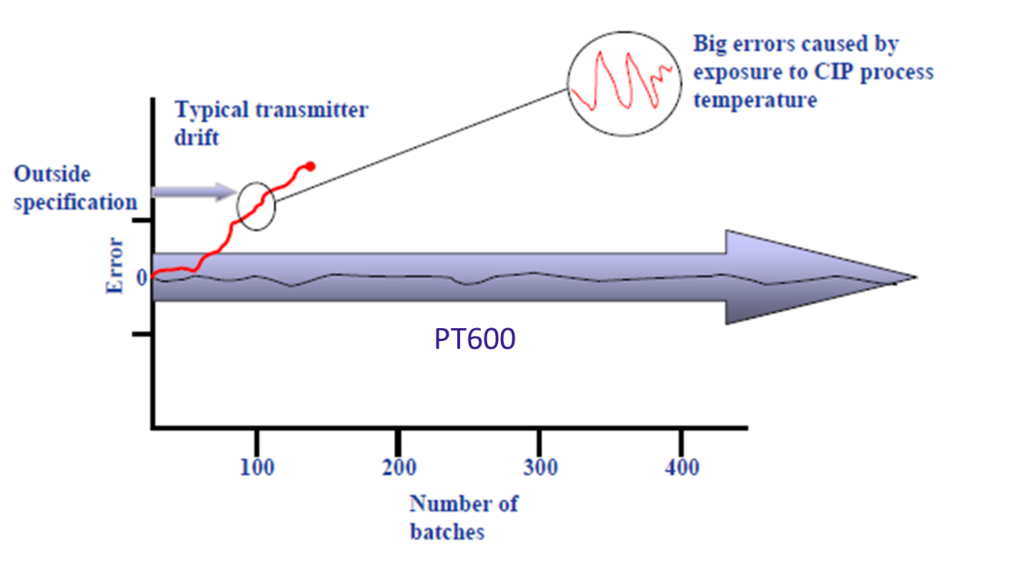
The unique concept with directly connected process connections without pressure intermedia eliminates temperature influence and provide a robust design. Full sensor compensation compensates for all errors, influence from sensor, influence from oil filling and influence from process connection. This solution enables high stability for CIP application (clean in place). Since PT-series are equipped with directly connected process connection the stability is ±0,05% for rapid temperature changes from +4˚C to +200 ˚C.
All connections are equipped with the unique gauge reference solution, designed in order that air passes cold surfaces closest to the pressure connection of the transmitter. Any humidity in the air will condense on these surfaces. The condensate flows out and the remaining air in the tube stays dry. Additionally, the reference pressure connection is designed to prevent flushing water from entering.
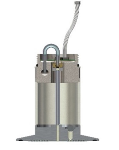
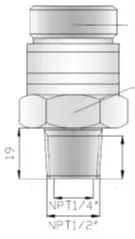
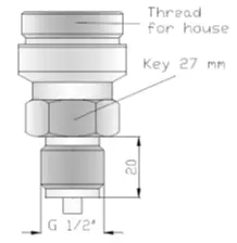
Threaded connection
Code 1 G½”
Code 2 NPT½”
Code O G½” with extended diaphragm
The threaded transmitter G 1/2” and NPT½” thread is intended for clean media, type O (extended diaphragm) is used for viscous media.
At a media temperature higher than 90⁰C, a cooling pipe is used to prevent too high temperature at the sensor.
The threaded connection is normally sufficient to keep the transmitter in place. At specific conditions or wall installation the transmitter can be supported and reinforced with an installation kit.
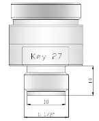
Threaded transmitter with extended diaphragm, G1½”.
Code 3
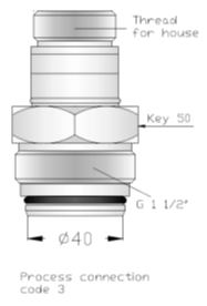
This transmitter connection with a connection G1½” thread.
The connection is intended for fibre-rich and viscous media and the extended front diaphragm is in connection with the media without any pocket inside the tank or pipe. An o-ring in the front keep the threads free from pulp and other particles.
Optional adapter is available forconnection to a 2″ thread and an optional welding sleeve for R1½”.
There are no additional requirements on the installation. The transmitter may also be connected inside a threaded R1½” cylinder, such as a pipe.
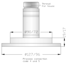
Flange pressure connections:
Code 4: Flange 80 mm/3”.
Code 5: Flange 50 mm/2”
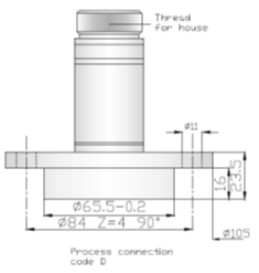
Code D: DRD flange.
A flange connected transmitter is intended for level measurement in open tanks with liquid media, even with fibre rich and/or viscous media. The risk of blockage is eliminated by the large area of the exposed diaphragm.
The transmitter is clamped between standard flange rings of ANSI or DIN type.
Removable during operation:
Code 6
The transmitter can be removed during operation and comprises three parts: The connection, a ball valve PN63, DN32 and welded casing/compression flange.
This connection type is intended for liquid media, even with viscous or fiber rich media. The extended diaphragm is in connection with the media without any pocket inside the tank or pipe. The compression flange is designed to fit an ANSI or DIN 80 mm/3” flange and may be installed to measure levels according to the hydrostatic principle
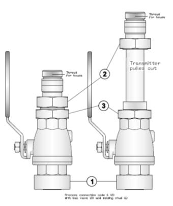
PASVE® connection
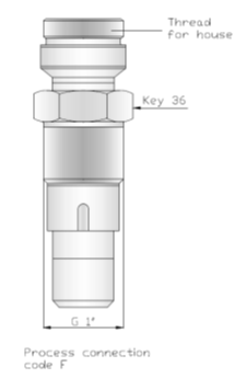
Code F
PASVE® connection fits to the PASVE® ball valve.
PASVE® is a ball-type mounting & service valve for level and pressure transmitters. PASVE® makes it simple to disconnect the transmitter from the process for maintenance and cleaning, without stopping the process or draining the tank.
See PASVE® valve instructions for mounting and handling.
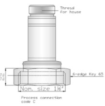
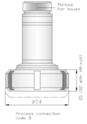
Hygienic screw connection.
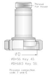
Code 7, 8, C, E
Screw connection giving a hygienic connection, for example, use in the Dairy industry. The exposed diaphragm has direct contact with the media which makes it possible for the transmitter to measure even viscous liquid media, with-out becoming silted up.
The pressure connection is installed in accordance with the Rd 60-6 connection of SMS 1146, DIN 405 and DIN 11851 or RJT standard. The pressure connection is screwed to the connector.
Clamp connections.
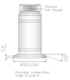
Code 9: TriClamp 38/1½”
Code A: TriClamp 51/2”
A clamp connected transmitter is used when special hygienic requirements are needed, such as those in the pharmaceutical industry. The design meets ISO 2852 and the transmitter is easy to install and remove.
If clamp connection is not available, the optional connector piece, clamping ring and gasket ring may be used. Contact customer center. Code 9 and A fulfills the demands for 3A standard 74-05.
Hygienic with front diaphragm.
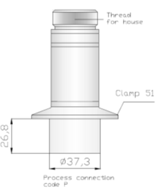
Code P
This connection is designed for level measurement in tanks with
V bottom. The design is done so that no media will remain on the diaphragm or gasket when the tank is emptied.
A specially designed welding stud and a Clamp ring (2”/51 mm) must be used for hygienic installation.
Factory calibration position: Horizontal (90 degree to drawing).
Pressure range: -0,1 to 2 MPa.
Code P fulfils the demands for 3A standard 74-05.
Varivent flange
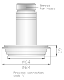
Code V
Varivent flange DN50 2”
The Varivent process connection is a flush flange connection. It is like the TriClamp connection in that it relies on a clamp to hold the flange of the sensor holder together with a matching flange on the process connection. Varivent connections use an o-ring seal around the internal diameter of the connection. Varivent connections are most found in breweries, dairies, and other food applications. They are sometimes known as Tuchenhagen connectors from the name of the company that invented them.
Varivent fulfils the demands for 3A standard 74-05.
Differential pressure transmitters
Code G
Differential Pressure with NPT ¼” internal threads.
Differential pressure transmitters can be used for measurement of levels in pressurized vessels, flow measurement in combination with orifice and many other applications. The transmitter can be mounted in any direction. To obtain easily zero adjusting and simpler mounting a standard valve block can be fitted.
Code H
Differential Pressure with flange connection
flange 50 mm/2” or 80 mm/3”) on the plus side and NPT ¼” on the minus side or vice versa. Flange connected transmitters must have the correct flange ring.
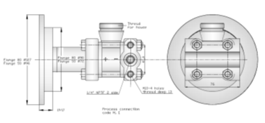
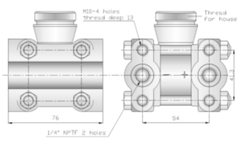
Connection with capillary tube
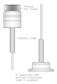
Code N
This connection is designed for use when the media have very high temperature or when close surroundings to the measuring point are very hot. The connection can be delivered with optional process connections.
Hygienic differential pressure connection
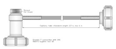
Code T
Hygienic differential pressure connection with capillary tube, this type of connection is mainly intended to be used for level measurement on pressurized tanks (with low or medium static pressure) and similar applications.
Type T can be manufactured with different types of process connections for example hygienic nut SMS Rd60-6 or clamp 38/51 (see the selection guide for possible choices).
For example, this type can replace two transmitters and a subtraction module with much better result.
Type T can also replace a traditional differential pressure transmitter in applications with low or medium static pressures, especially if there are hygienic demands.
Connection | Hygienic nut | Removable during operation | Clamp on | Threaded
| Flanges | Differential pressure |
Pressure range | 0,3 to 80 bar | 0,35 to 20 bar | 0,35 to 40 bar | 0,5 to 200 bar | 0,5 to 40 bar | 6 mbar to 10 bar |
Accuracy | ±0,075…0,25% | ±0,075…0,25% | ±0,075…0,25% | ±0,075…0,25% | ±0,075…0,25% | ±0,075…0,25% |
Media temp | 150⁰C | 150⁰C | 150⁰C | 90…150⁰C | 150⁰C | 90…150⁰C |
Diaphragm | 316L | 316L | 316L | 316L | 316L SAF205 (duplex) | 316L |
FDA approved | √ | √ | √ | √ | √ | √ |
Vacuum proof | √ | √ | √ | √ | √ | √ |
Types | SMS38 1½” | Ball valve | Clamp 38, 51 | G½”, G½” front bounded diaphragm | Flange 50 mm (2”)
| NPT ¼” |


